Saturday, December 22, 2012
Cores and Processors
In simpler terms,
Core: Cores are what handle the arbitrary mathematical and logical workloads. They take high level machine instructions (x86, ARM, MIPS, etc...) and 'decode' them into physical circuit operations. Many other parts of the system, such as GPUs and chipsets operate in a similar manner but are designed with specific purposes in mind which makes them more efficient at these particular tasks. CPU cores are designed with a general purpose, making them jacks of all trades.
Processor / CPU: The combination of one or more 'cores' with supporting hardware and shared resources.
Processor package: The physical casing in which one or more processors or CPUs is contained. The pinout from the package is what allows the processor to interface with the rest of the system. Some processor packages may contain more than one processor die inside of them, or may have the cores and shared resources on separate pieces. The contents of the processor package and how it is organized are up to the manufacturer, hence the distinction between Processor and Processor Package.
For example, the Core 2 Quad processors were actually two individual Core 2 Duo processors in the same package with some very simple supporting hardware to allow them to work together. This stands in contrast to the more modern Sandybridge processors which have all 4 cores and supporting hardware on one chip, a far more efficient design.
The terms 'Processor', 'Core', and 'CPU' are all poorly defined and have undergone many changes in meaning over the year as computer architectures have evolved and changed.
Under modern terminology, 'Processor' and 'CPU' mean more or less exactly the same thing. It would be more accurate to refer to the 'processor package' because there's no real standard to what a the package contains. Very old CPUs from 15-20 years ago contained little more than the bare minimum to execute tasks.
They contained the ALUs, fetch and decode hardware, Instruction pipeline, Interrupt handling hardware, some IO control hardware and that's about it. After this, cache memory was added to the CPU to improve execution
Then, the execution parts of the processor were duplicated. The ALUs, fetch and decode, instruction pipline, and some cache memory were organized into what we now call "cores". Each core is capable of functioning on its own and contain all the resources necessary to perform computational tasks that do not involve interacting with components outside the CPU. IO Control, interrupt handling, etc... were all shared between all the cores.
More recently the memory controller itself has been moved into the CPU package. It sits along side the CPU cores but it is not part of them. Thus it is part of the package, or part of the processor/CPU but it is not part of the 'cores'. Intel used to specifically refer to this as the 'un-core'.
This gets even more complicated when we talk about systems which have multiple physical processor packages installed. Many server and workstation platforms can have 2, 4, or even more processor packages installed. Each processor package contains the same hardware.
Thus, the number of 'cores' in a machine can be computed by taking the number of cores per package and multiplying it by the number of packages in the system. A computer which has two quad core processors has the same number of cores as a computer which has a single octal core processor.
Here is an image of a motherboard that has 4 processor sockets
http://i1-news.softpedia-static.co [...] -RAM-2.jpg
Each one of those processor sockets (the flat ones with all the pins and metal coverings) can hold an AMD Opteron 6100 series processor. Each Opteron 6100 processor has either 8 or 12 cores inside which means that particular system can have between 8 (a single 8-core processor installed) and 48 cores present (4 12-core processors installed).
A dual core processor for a computer is a central processing unit (CPU) that has two separate cores on the same die, each with its own cache. It essentially is two microprocessors in one. This type of CPU is widely available from many manufacturers. Other types of multi-core processors also have been developed, including quad-core processors with four cores each, hexa-core processors with six, octa-core processors with eight and many-core processors with an even larger number of cores.
In a single-core or traditional processor, the CPU is fed strings of instructions that it must order, execute, then selectively store in its cache for quick retrieval. When data outside the cache is required, it is retrieved through the system bus from random access memory (RAM) or from storage devices. Accessing these slows down performance to the maximum speed that the bus, RAM or storage device will allow, which is far slower than the speed of the CPU.
This situation is compounded when the computer user is multi-tasking. In this case, the processor must switch back and forth between two or more sets of data streams and programs. CPU resources are depleted, and performance suffers.
In a dual core processor, each core handles incoming data strings simultaneously to improve efficiency. Just as two heads are better than one, so are two hands. When one core is executing, the other can be accessing the system bus or executing its own code.
To utilize a dual core processor, the operating system must be able to recognize multi-threading, and the software must have simultaneous multi-threading technology (SMT) written into its code. SMT enables parallel multi-threading, wherein the cores are served multi-threaded instructions in parallel. Without SMT, the software will recognize only one core. SMT also is used with multi-processor systems that are common to servers.
A dual core processor is different from a multi-processor system. In the latter, there are two separate CPUs with their own resources. In the former, resources are shared, and the cores reside on the same chip. A multi-processor system is faster than a system with a dual core processor, and a dual core system is faster than a single-core system, when everything else is equal.
An attractive value of dual core processors is that they do not require new motherboards but can be used in existing boards that feature the correct sockets. For the average user, the difference in performance will be most noticeable during multi-tasking, until more software is SMT aware. Servers that are running multiple dual core processors will see an appreciable increase in performance.
Monday, November 5, 2012
Wind ??
Wind, the movement of air over the earth's surface. The upward movement of air is known as an updraft; movement downward, as a downdraft. Wind is an important element of weather.
Wind is caused by differences in atmospheric pressure created, in large part, by the unequal heating of the earth's surface by the sun. Air moves from a region of higher pressure to one of lower pressure and this movement is wind. Any difference in pressure will cause wind, but the greater the difference the stronger the wind.
Wind is the flow of gases on a large scale. On Earth, wind consists of the bulk movement of air. In outer space, solar wind is the movement of gases or charged particles from the sun through space, while planetary wind is the outgassing of light chemical elements from a planet's atmosphere into space.
Winds are commonly classified by their spatial scale, their speed, the types of forces that cause them, the regions in which they occur, and their effect. The strongest observed winds on a planet in our solar system occur on Neptune and Saturn.
In meteorology, winds are often referred to according to their strength, and the direction from which the wind is blowing. Short bursts of high speed wind are termed gusts. Strong winds of intermediate duration (around one minute) are termed squalls. Long-duration winds have various names associated with their average strength, such as breeze, gale, storm, hurricane, and typhoon.
Wind occurs on a range of scales, from thunderstorm flows lasting tens of minutes, to local breezes generated by heating of land surfaces and lasting a few hours, to global winds resulting from the difference in absorption of solar energy between the climate zones on Earth. The two main causes of large-scale atmospheric circulation are the differential heating between the equator and the poles, and the rotation of the planet (Coriolis effect). Within the tropics, thermal low circulations over terrain and high plateaus can drive monsoon circulations. In coastal areas the sea breeze/land breeze cycle can define local winds; in areas that have variable terrain, mountain and valley breezes can dominate local winds.
What causes wind?
Wind is caused by air flowing from high pressure to low pressure. Since the Earth is rotating, however, the air does not flow directly from high to low pressure, but it is deflected to the right (in the Northern Hemisphere; to the left in the Southern Hemisphere), so that the wind flows mostly around the high and low pressure areas. This effect of the wind "feeling the Earth turn underneath it" is important for very large and long-lived pressure systems. For small, short-lived systems (such as in the cold outflow of a thunderstorm) the wind will flow directly from high pressure to low pressure.
Wind is caused by air flowing from high pressure to low pressure. Since the Earth is rotating, however, the air does not flow directly from high to low pressure, but it is deflected to the right (in the Northern Hemisphere; to the left in the Southern Hemisphere), so that the wind flows mostly around the high and low pressure areas. This effect of the wind "feeling the Earth turn underneath it" is important for very large and long-lived pressure systems. For small, short-lived systems (such as in the cold outflow of a thunderstorm) the wind will flow directly from high pressure to low pressure.
The closer the high and low pressure areas are together, the stronger the "pressure gradient", and the stronger the winds. On weather maps, lines of constant pressure are drawn (as in the example, above) which are called "isobars". These isobars are usually labeled with their pressure value in millibars (mb). The closer these lines are together, the stronger the wind.
Tuesday, October 2, 2012
Wiring Color Codes
Wiring for AC and DC power distribution branch circuits are color coded for identification of individual wires. In some jurisdictions all wire colors are specified in legal documents. In other jurisdictions, only a few conductor colors are so codified. In that case, local custom dictates the “optional” wire colors.
IEC, AC: Most of Europe abides by IEC (International Electrotechnical Commission) wiring color codes for AC branch circuits. These are listed in Table below. The older color codes in the table reflect the previous style which did not account for proper phase rotation. The protective ground wire (listed as green-yellow) is green with yellow stripe.
IEC (most of Europe) AC power circuit wiring color codes.
| Function | label | Color, IEC | Color, old IEC |
|---|---|---|---|
| Protective earth | PE | green-yellow | green-yellow |
| Neutral | N | blue | blue |
| Line, single phase | L | brown | brown or black |
| Line, 3-phase | L1 | brown | brown or black |
| Line, 3-phase | L2 | black | brown or black |
| Line, 3-phase | L3 | grey | brown or black |
UK, AC: The United Kingdom now follows the IEC AC wiring color codes. Table below lists these along with the obsolete domestic color codes. For adding new colored wiring to existing old colored wiring see Cook. [PCk]
UK AC power circuit wiring color codes.
| Function | label | Color, IEC | Old UK color |
|---|---|---|---|
| Protective earth | PE | green-yellow | green-yellow |
| Neutral | N | blue | black |
| Line, single phase | L | brown | red |
| Line, 3-phase | L1 | brown | red |
| Line, 3-phase | L2 | black | yellow |
| Line, 3-phase | L3 | grey | blue |
US, AC:The US National Electrical Code only mandates white (or grey) for the neutral power conductor and bare copper, green, or green with yellow stripe for the protective ground. In principle any other colors except these may be used for the power conductors. The colors adopted as local practice are shown in Table below. Black, red, and blue are used for 208 VAC three-phase; brown, orange and yellow are used for 480 VAC. Conductors larger than #6 AWG are only available in black and are color taped at the ends.
US AC power circuit wiring color codes.
| Function | label | Color, common | Color, alternative |
|---|---|---|---|
| Protective ground | PG | bare, green, or green-yellow | green |
| Neutral | N | white | grey |
| Line, single phase | L | black or red (2nd hot) | |
| Line, 3-phase | L1 | black | brown |
| Line, 3-phase | L2 | red | orange |
| Line, 3-phase | L3 | blue | yellow |
Canada: Canadian wiring is governed by the CEC (Canadian Electric Code). See Table below. The protective ground is green or green with yellow stripe. The neutral is white, the hot (live or active) single phase wires are black , and red in the case of a second active. Three-phase lines are red, black, and blue.
Canada AC power circuit wiring color codes.
| Function | label | Color, common |
|---|---|---|
| Protective ground | PG | green or green-yellow |
| Neutral | N | white |
| Line, single phase | L | black or red (2nd hot) |
| Line, 3-phase | L1 | red |
| Line, 3-phase | L2 | black |
| Line, 3-phase | L3 | blue |
IEC, DC: DC power installations, for example, solar power and computer data centers, use color coding which follows the AC standards. The IEC color standard for DC power cables is listed in Table below, adapted from Table 2, Cook. [PCk]
IEC DC power circuit wiring color codes.
| Function | label | Color |
|---|---|---|
| Protective earth | PE | green-yellow |
| 2-wire unearthed DC Power System | ||
| Positive | L+ | brown |
| Negative | L- | grey |
| 2-wire earthed DC Power System | ||
| Positive (of a negative earthed) circuit | L+ | brown |
| Negative (of a negative earthed) circuit | M | blue |
| Positive (of a positive earthed) circuit | M | blue |
| Negative (of a positive earthed) circuit | L- | grey |
| 3-wire earthed DC Power System | ||
| Positive | L+ | brown |
| Mid-wire | M | blue |
| Negative | L- | grey |
US DC power: The US National Electrical Code (for both AC and DC) mandates that the grounded neutral conductor of a power system be white or grey. The protective ground must be bare, green or green-yellow striped. Hot (active) wires may be any other colors except these. However, common practice (per local electrical inspectors) is for the first hot (live or active) wire to be black and the second hot to be red. The recommendations in Table below are by Wiles. [JWi] He makes no recommendation for ungrounded power system colors. Usage of the ungrounded system is discouraged for safety. However, red (+) and black (-) follows the coloring of the grounded systems in the table.
US recommended DC power circuit wiring color codes.
| Function | label | Color |
|---|---|---|
| Protective ground | PG | bare, green, or green-yellow |
| 2-wire ungrounded DC Power System | ||
| Positive | L+ | no recommendation (red) |
| Negative | L- | no recommendation (black) |
| 2-wire grounded DC Power System | ||
| Positive (of a negative grounded) circuit | L+ | red |
| Negative (of a negative grounded) circuit | N | white |
| Positive (of a positive grounded) circuit | N | white |
| Negative (of a positive grounded) circuit | L- | black |
| 3-wire grounded DC Power System | ||
| Positive | L+ | red |
| Mid-wire (center tap) | N | white |
| Negative | L- | black |
Single phase vs three phase
What's the difference between single phase and three phase?
Electricity is either connected at 230 or 240 volts (single-phase, which accounts for the majority of domestic situations), or 400 and 415 Volts (three-phase). The latter is better suited to providing for powerful appliances and fixed plant, and is more commonly used by industrial and larger commercial users.
Single-phase comes to the home with two wires: active and neutral. The neutral wire is connected to earth (water pipe, earth stake, etc.) at the switchboard.
Three-phase has four wires: three actives (called phases) and one neutral. The neutral wire is earthed at the switchboard

1. Big electric motors (usually more than 2 kilowatt) need three-phase power. This includes large workshop equipment.
2. Large domestic installations sometimes have three-phase because it distributes the total load in a way that ensures that the current in each phase is lower.
For example: Imagine the total electrical load is 24 kilowatts (24,000 watts - that's a lot for a domestic installation). For a normal, single-phase power supply at 240 volts, the maximum current would be 100 amps. The current in amps multiplied by voltage in volts gives power in watts (Power = voltage x current).
If a three-phase supply is available, then the 24,000 watts are divided by 3, meaning that 8000 watts is being used per phase. Now the current per phase is also down to a third of what it would be with a single phase supply (about 30 amps per phase, rather than 100). Putting that in perspective, ten 100 watt lighting fixtures represent 1 kilowatt of power, which equates to a bit under 40 amps.
A word of caution though: connection fees for three-phase are higher, and there are fixed annual charges as well for three-phase so don’t contemplate it for a new home unless you really need it.
Rural connections and SWER
Depending on your locality you may be connected to a SWER line. These are used in many country areas. Single wire, earth return (SWER) delivers single phase power. It’s an economical way of distributing power, because only one transmission line (active) is needed. There is no neutral - instead the earth is employed as the ‘return’ conductor.
If three-phase motors have to be used, a single-phase to three-phase power converter has to be installed by the electricity consumer
3 phase Y and delta
Three-phase Y and Delta configurations
Initially we explored the idea of three-phase power systems by connecting three voltage sources together in what is commonly known as the “Y” (or “star”) configuration. This configuration of voltage sources is characterized by a common connection point joining one side of each source. (Figure below)
Three-phase “Y” connection has three voltage sources connected to a common point.
If we draw a circuit showing each voltage source to be a coil of wire (alternator or transformer winding) and do some slight rearranging, the “Y” configuration becomes more obvious in Figure below.
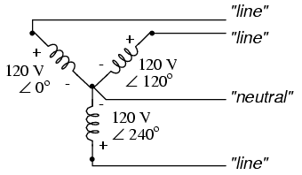
Three-phase, four-wire “Y” connection uses a "common" fourth wire.
The three conductors leading away from the voltage sources (windings) toward a load are typically called lines, while the windings themselves are typically called phases. In a Y-connected system, there may or may not (Figure below) be a neutral wire attached at the junction point in the middle, although it certainly helps alleviate potential problems should one element of a three-phase load fail open, as discussed earlier.

Three-phase, three-wire “Y” connection does not use the neutral wire.
When we measure voltage and current in three-phase systems, we need to be specific as to where we're measuring. Line voltage refers to the amount of voltage measured between any two line conductors in a balanced three-phase system. With the above circuit, the line voltage is roughly 208 volts. Phase voltage refers to the voltage measured across any one component (source winding or load impedance) in a balanced three-phase source or load. For the circuit shown above, the phase voltage is 120 volts. The terms line current and phase current follow the same logic: the former referring to current through any one line conductor, and the latter to current through any one component.
Y-connected sources and loads always have line voltages greater than phase voltages, and line currents equal to phase currents. If the Y-connected source or load is balanced, the line voltage will be equal to the phase voltage times the square root of 3:

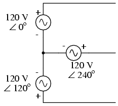
However, the “Y” configuration is not the only valid one for connecting three-phase voltage source or load elements together. Another configuration is known as the “Delta,” for its geometric resemblance to the Greek letter of the same name (Δ). Take close notice of the polarity for each winding in Figure below.

Three-phase, three-wire Δ connection has no common.
At first glance it seems as though three voltage sources like this would create a short-circuit, electrons flowing around the triangle with nothing but the internal impedance of the windings to hold them back. Due to the phase angles of these three voltage sources, however, this is not the case.
One quick check of this is to use Kirchhoff's Voltage Law to see if the three voltages around the loop add up to zero. If they do, then there will be no voltage available to push current around and around that loop, and consequently there will be no circulating current. Starting with the top winding and progressing counter-clockwise, our KVL expression looks something like this:

Indeed, if we add these three vector quantities together, they do add up to zero. Another way to verify the fact that these three voltage sources can be connected together in a loop without resulting in circulating currents is to open up the loop at one junction point and calculate voltage across the break: (Figure below)

Voltage across open Δ should be zero.
Starting with the right winding (120 V ∠ 120o) and progressing counter-clockwise, our KVL equation looks like this:

Sure enough, there will be zero voltage across the break, telling us that no current will circulate within the triangular loop of windings when that connection is made complete.
Having established that a Δ-connected three-phase voltage source will not burn itself to a crisp due to circulating currents, we turn to its practical use as a source of power in three-phase circuits. Because each pair of line conductors is connected directly across a single winding in a Δ circuit, the line voltage will be equal to the phase voltage. Conversely, because each line conductor attaches at a node between two windings, the line current will be the vector sum of the two joining phase currents. Not surprisingly, the resulting equations for a Δ configuration are as follows:

Let's see how this works in an example circuit: (Figure below)

The load on the Δ source is wired in a Δ.
With each load resistance receiving 120 volts from its respective phase winding at the source, the current in each phase of this circuit will be 83.33 amps:

So each line current in this three-phase power system is equal to 144.34 amps, which is substantially more than the line currents in the Y-connected system we looked at earlier. One might wonder if we've lost all the advantages of three-phase power here, given the fact that we have such greater conductor currents, necessitating thicker, more costly wire. The answer is no. Although this circuit would require three number 1 gage copper conductors (at 1000 feet of distance between source and load this equates to a little over 750 pounds of copper for the whole system), it is still less than the 1000+ pounds of copper required for a single-phase system delivering the same power (30 kW) at the same voltage (120 volts conductor-to-conductor).
One distinct advantage of a Δ-connected system is its lack of a neutral wire. With a Y-connected system, a neutral wire was needed in case one of the phase loads were to fail open (or be turned off), in order to keep the phase voltages at the load from changing. This is not necessary (or even possible!) in a Δ-connected circuit. With each load phase element directly connected across a respective source phase winding, the phase voltage will be constant regardless of open failures in the load elements.
Perhaps the greatest advantage of the Δ-connected source is its fault tolerance. It is possible for one of the windings in a Δ-connected three-phase source to fail open (Figure below) without affecting load voltage or current!

Even with a source winding failure, the line voltage is still 120 V, and load phase voltage is still 120 V. The only difference is extra current in the remaining functional source windings.
The only consequence of a source winding failing open for a Δ-connected source is increased phase current in the remaining windings. Compare this fault tolerance with a Y-connected system suffering an open source winding in Figure below.

Open “Y” source winding halves the voltage on two loads of a Δ connected load.
With a Δ-connected load, two of the resistances suffer reduced voltage while one remains at the original line voltage, 208. A Y-connected load suffers an even worse fate (Figure below) with the same winding failure in a Y-connected source

Open source winding of a "Y-Y" system halves the voltage on two loads, and looses one load entirely.
In this case, two load resistances suffer reduced voltage while the third loses supply voltage completely! For this reason, Δ-connected sources are preferred for reliability. However, if dual voltages are needed (e.g. 120/208) or preferred for lower line currents, Y-connected systems are the configuration of choice.
- REVIEW:
- The conductors connected to the three points of a three-phase source or load are called lines.
- The three components comprising a three-phase source or load are called phases.
- Line voltage is the voltage measured between any two lines in a three-phase circuit.
- Phase voltage is the voltage measured across a single component in a three-phase source or load.
- Line current is the current through any one line between a three-phase source and load.
- Phase current is the current through any one component comprising a three-phase source or load.
- In balanced “Y” circuits, line voltage is equal to phase voltage times the square root of 3, while line current is equal to phase current.
-
- In balanced Δ circuits, line voltage is equal to phase voltage, while line current is equal to phase current times the square root of 3.
-
- Δ-connected three-phase voltage sources give greater reliability in the event of winding failure than Y-connected sources. However, Y-connected sources can deliver the same amount of power with less line current than Δ-connected sources.
Three Phase Power
Three-phase electric power is a common method of alternating current electric power generation, transmission, and distribution. It is a type of polyphase system and is the most common method used by grids worldwide to transfer power. It is also used to power large motors and other heavy loads. A three-phase system is generally more economical than others because it uses less conductor material to transmit electric power than equivalent single-phase or two-phase systems at the same voltage. The three-phase system was introduced and patented by Nikola Tesla in the years from 1887 to 1888.
In a three-phase system, three circuit conductors carry three alternating currents (of the same frequency) which reach their instantaneous peak values at different times. Taking one conductor as the reference, the other two currents are delayed in time by one-third and two-thirds of one cycle of the electric current. This delay between phases has the effect of giving constant power transfer over each cycle of the current and also makes it possible to produce a rotating magnetic field in an electric motor.
Three-phase systems may or may not have a neutral wire. A neutral wire allows the three-phase system to use a higher voltage while still supporting lower-voltage single-phase appliances. In high-voltage distribution situations, it is common not to have a neutral wire as the loads can simply be connected between phases (phase-phase connection).
Three-phase has properties that make it very desirable in electric power systems:
The phase currents tend to cancel out one another, summing to zero in the case of a linear balanced load. This makes it possible to eliminate or reduce the size of the neutral conductor; all the phase conductors carry the same current and so can be the same size, for a balanced load.
Power transfer into a linear balanced load is constant, which helps to reduce generator and motor vibrations.
Three-phase systems can produce a magnetic field that rotates in a specified direction, which simplifies the design of electric motors.
It is precisely for this reason that it is so often used in the Commercial and Industrial properties. Whether it's your local garage, shop,factory or office block you will most often find a 3 phase 415 volt supply. Extra care must be taken when working with this system as an electric shock from 415 volts can quite often be fatal, where as 230/240 volts, without RCD protection, in the majority of cases will just give you a hard belt.

The voltage between two lines (for example 'L1' and 'L2') is called the line to line (or phase to phase) voltage. The voltage across each winding (for example between 'L1' and 'N' is called the line to neutral (or phase voltage).
The line to line voltage is the vector sum of the phase to phase voltage across each winding. This is not the same as the arithmetic sum and is given by the following equation:
Line to Line Voltage (VLL)
 | Example: Line to Line Voltage (VLL)       |
A 3 Phase-Wye connected system consists of three hot lines, or phases, commonly referred to as X, Y, Z, a neutral, and a ground wire for a total of five wires in a power distribution cable.
In North America the most common 3 Phase-Y voltages are either 120/208 VAC or 277/480 VAC, while internationally the most common 3 Phase voltage is 230/400 VAC. The lower voltage in each case is the country’s standard utilization voltage and is measured Line-to-Neutral, while the higher voltage is measured Line-to-Line. The Line-to-Line voltage is always 1.732 times higher than the Line-to-Neutral voltage in a Wye configured 3 Phase system.
The line current supplied to the load is also the same as the phase current. It is important to note that when all three “Hot” phases of the system are loaded equally, the net current draw in the neutral line is zero!

3 Phase Delta (Δ)A 3 Phase-Delta connected system consists of three hot lines, commonly referred to as X, Y, Z, and a ground wire for a total of four wires in a power distribution cable.In North America the most common 3 Phase-Δ voltages are either 208VAC or 240VAC, while internationally the most common 3 Phase voltage is 230 VAC. These phase voltages are measured Line-to-Line and are typically the country’s standard utilization voltage. Since there is no neutral line in a Delta-connected system, there is no Line-to-Neutral voltage! However, the line current in a Delta-connected system is 1.732 times the phase current supplied to the load(s). Proper care must be taken to correctly size cables in a Delta system because the line currents are much higher than the load (or phase) currents. Delta systems typically have lower line voltages but higher line currents than Wye-connected systems. |

Subscribe to:
Posts (Atom)